To set the scene, at the start of the year, out of pretty much no where, I was invited to be part of a 6 man CanSat team. For those who don’t know what that is (i.e me 6 months ago…), its a team of teenagers that get together and build a little probe thing with some sensors and a parachute that fits neatly in a soda can. Said soda can is then launched up a couple hundred metres, and it sends down telemetry as it ascends and descends. Pretty cool!
As part of the project, our very cool radio man decided to design his own antenna, and came up with the brilliant idea of designing a mount to get the antenna to point at the CanSat as is ascends and descends. Me being the moron I was thought that was pretty easy, and so I started designing the mount :].
First Iterations#
As is painfully obvious from these first iterations, I was clearly unaware of the scale of what I was trying to move around. At least it serves the purpose of padding out this article..
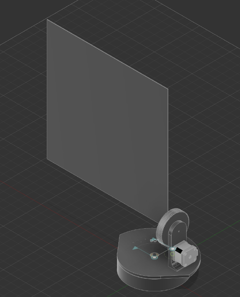
The initial design idea I had was a small tablet mounted device. It would have a cylindrical extrusion, with teeth along the inner surface. An orbital gear would spin around the inner circumference. Said orbital gear would be drive by a NEMA 17, and mounted to the rotating base. That gives us the Pan component of its articulation. For the the Tilt component, its just a simple gear ratio and a bracket to hold it perpendicular to the Pan axis. Enough waffling, here are pictures:
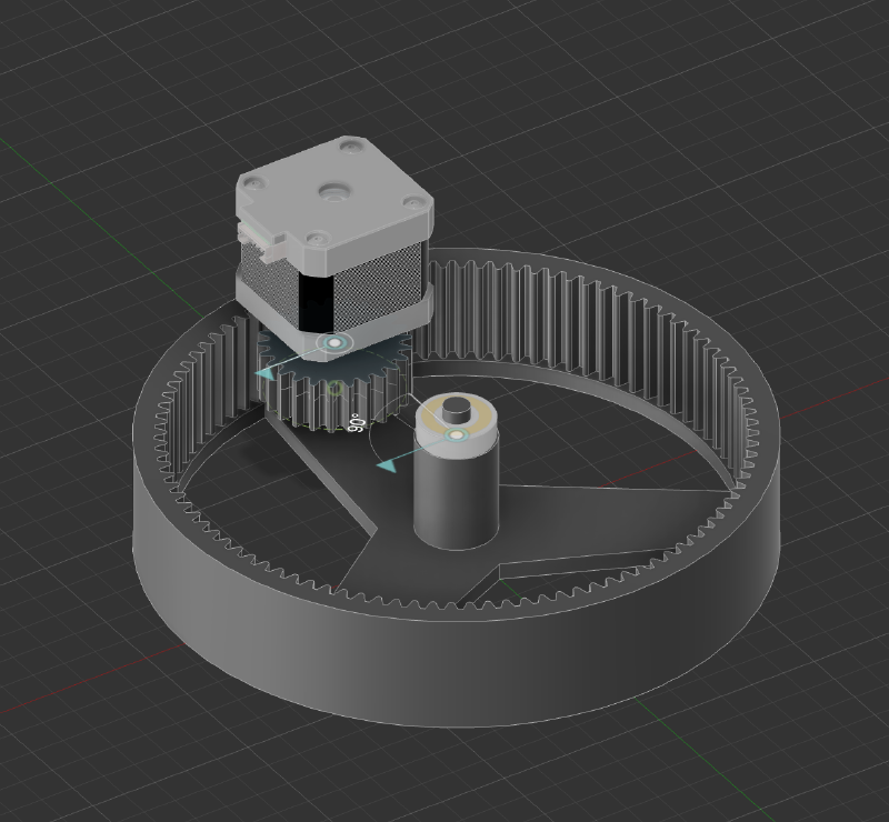
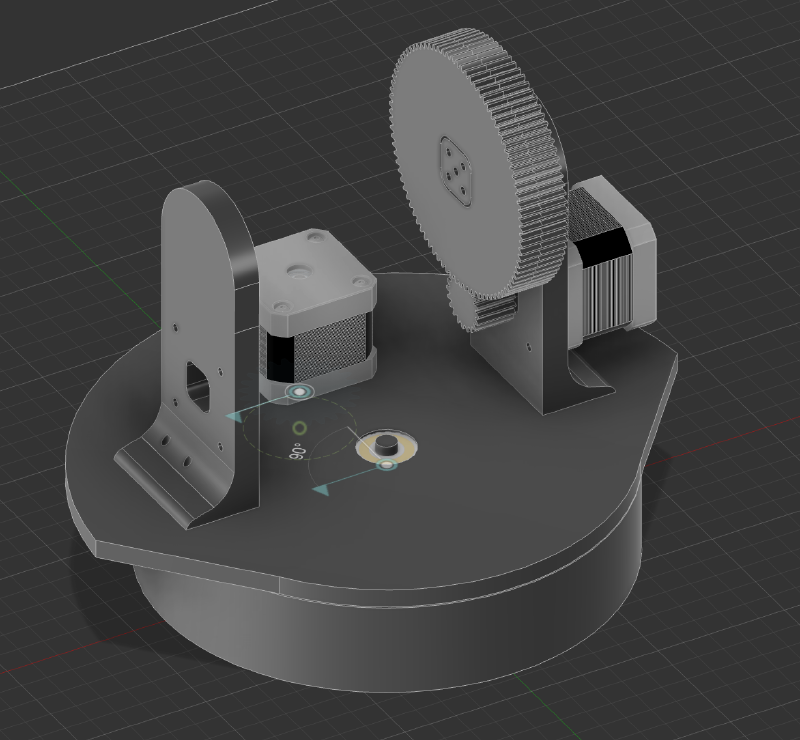
It looks pretty cool. My mounting solution was a rod going in between it onto which I would figure out a way to mount the antenna. What could go wrong eh?
Then I was made aware of the fact that the antenna has to sort of point up REALLY quickly, since we’re pretty close to the launch of course, and the rocket gets to altitude (300m) in about 8s. Thats just a bit fast (you’d struggle keeping up with that using your own neck). Heres a cool little diagram that I made as part of our CDR.
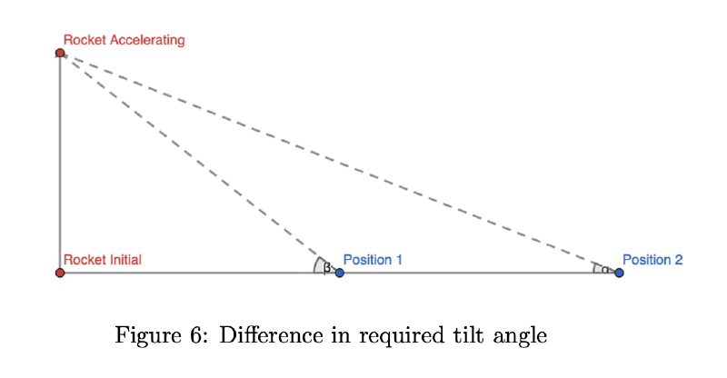
That coupled with me actually modelling in a placeholder antenna made me realise how stupid my design is. Fun!
So that was the very short lived life of the first iteration…
Actual Design#
The actual design is something I’m far more proud of. It was heavily inspired by a Instructable I saw, but I cannot for the life of me find the original. I’m not sure if its been taken down, or I’m being incompetent, but yeah..
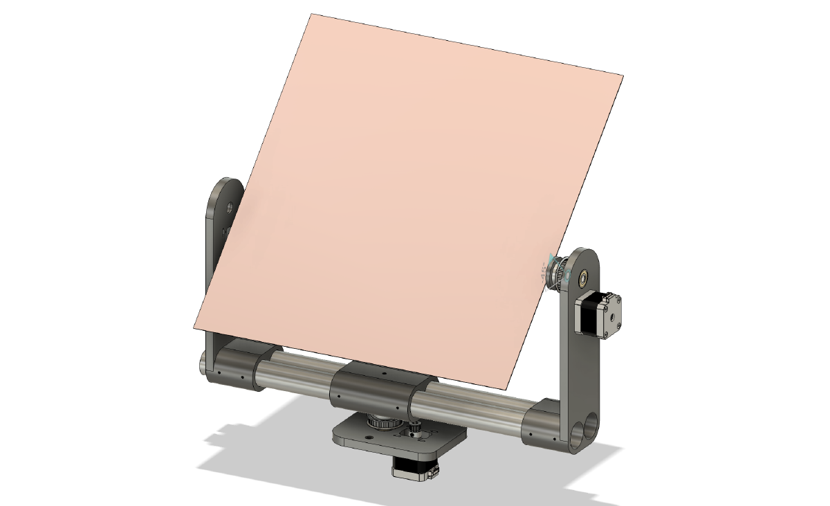
I did of course design it around the design principle they used. It uses GT2 pulley for a more robust gear ratio, and aluminium poles for the base. It boasts an adjustable mount for the antenna, and much much higher load capacity since the antenna counter balances itself by being mounted centrally. Very fun!
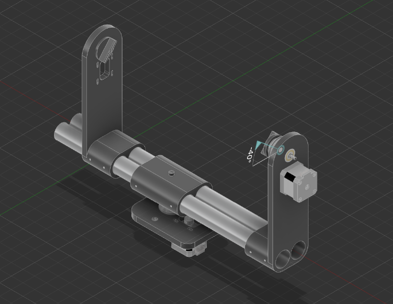
With the patch antenna mounted, it looks like this:

The plan was to then mount the antenna onto a tripod I had lying around, et voila. The electronics are very trivial, I won’t bother going into them in detail. In brief, its just a Pi Pico running a python script to control 2 steppers using stepper drivers and a 24V power supply. Simple as is. The tracking software is something I would have loved to get into, but we didn’t make finals sadly, and this project had hit the end of the run.
I did end up building it, and taking it to our regional launches. I can’t find photos of the actual mount right now, but when I do, and when I remember to add them, they’ll be attached below :]
The mount itself worked a charm, it was a but wobbly when I had to disassemble and re-assemble it at sight, but those kinks could easily be worked out with some better tolerance-d parts.
This janky mount did in fact also get its own BBC interview, but they didn’t decide that it was cool enough to make the air (though they thought us explaining a Power Supply was good enough to make B-Roll). BBC does BBC things..
All the files will be available (eventually) on my GitHub, if you’re interested for whatever reason.