
To be transparent, this is a write up that is being written (20/01/2024) two years from actually commencing this project. By no means is my account 100% factually accurate (my memory timeouts after a week..). But I thought I’d put my, what were definitely, valiant efforts, onto paper, and perhaps guilt future me into revisiting the cool idea, that the stupid 13 year old me left me afraid of. To clarify, this is by no means a guide, or even a real starting point on attempting this project yourself, just my personal experience.
So to set the scene, I was 13. I was stupid (as aforementioned). I saw a cool magnetic levitator somewhere on the internet. I was like “I could make that”. To spoil the story, turns out I couldn’t. In retrospect, this was rather obvious. Had I ever designed a PCB before? No. Had I ever come across PID control? No. Did I know a singular thing about op-amps? No (heck I didn’t even know what Kirchoff’s Laws, let alone be able to set Op-Amp gains). Point being I was incompetent, and delusional. In my experience, you can get away with either one of them, but both of them, at the same time? Not possible. Of course, I took that personally.
So what exactly was I trying to build. I think the name, Magnetic Levitator does an apt job of describing it, but if not, circular magnet go floaty floaty (with no string that is). The principle behind it was deceptively simple. You have four electromagnets in a grid. In the middle you house two or three hall-effect sensors (for x, y and the less necessary z axis of the platform) and some permanent magnets in the outer ring for stability. The outer magnets would pull the platform down, and the electromagnets would be repelling it. The sensors in the middle would read the fluctuating magnetic field, and with some clever code you would instruct the magnet to either push harder, or push softer, depending on it’s attitude. I thought I could get away with simple proportional error scaling, but oh how I was wrong. PID beckoned.
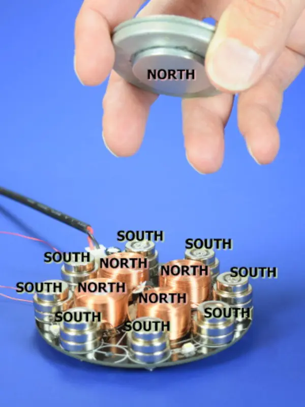
If you ever wondered why you couldn’t achieve this without implementing a negative feedback loop as described, its because of Earnshaw’s Theorem. Put simply, you can’t maintain a stable (returns to its home position) equilibrium using only the electrostatic interaction of the charges. Put simpler, it can’t be stable using only the charges of the permanent magnets. The math here does get a bit tricky, beyond my comprehension now, as it was then too. But taking it at face value, it prevents you from levitating easily.
There are ways around this. One notable way of achieving levitation without much effort is to invert the setup. You hang the electromagnet upside down (on top of the target), and you quickly switch the polarity of it between North and South to repel and attract your target. It practically eliminates the side to side variations, and so only has to account for the vertical component. With some clever tuning you can achieve this without a sensor at all (though it does make it significantly easier).
If you do happen to have a sizeable budget, you can use superconductive levitation, which works without any kind of electronics. You cool a material till its below its critical point, and voila, it floats. For more details, look into the Meissner effect.
Getting back to the project, I grew up messing around with electronics a fair amount. Sure I wasn’t some child genius building radios and stuff at the age of 9, but I racked up a fair amount of experience tinkering with electronics modules, microcontrollers, and some code to wrap it all up. Though never had I messed around with actually designing stuff. That’s scary.
So with learning PCB design, it did take me a solid 4 months before I had a decent iteration to work from (between moving houses and stuff, but a solid 3 weeks of learning stuff perhaps?). A lot of it was spent bogged down in the software. I messed around with different tools, auto-routing, different workflows, before I even understood what I was doing. Just learn the tool people. Worry about whether or not its good later. And if it so happens that another tool is better, defend the tool you were using till the grave. Its that simple.
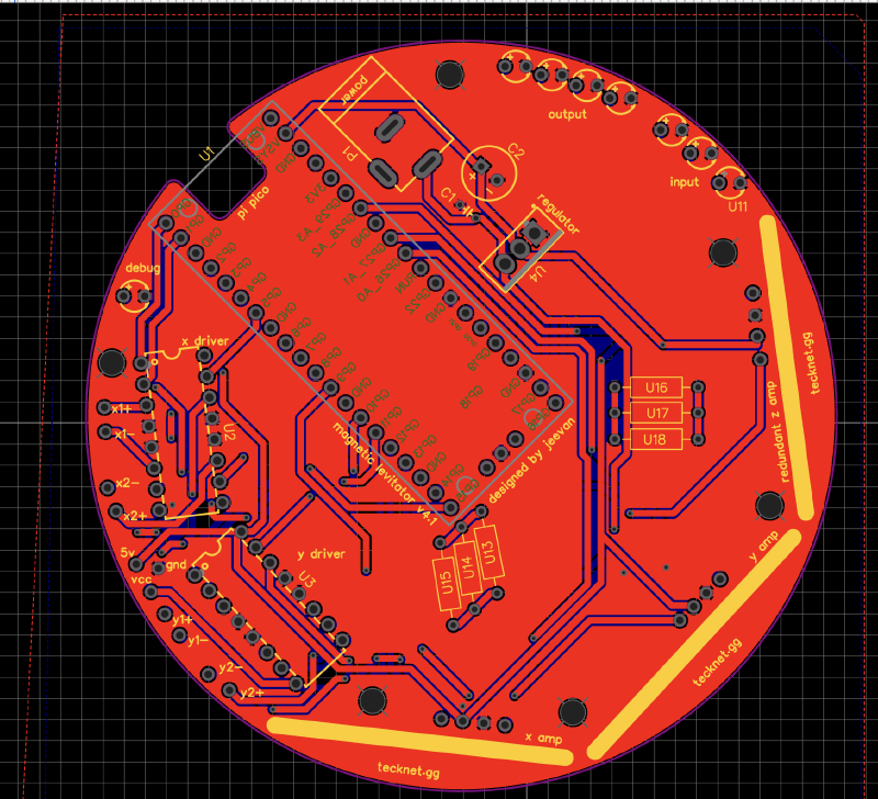
Here is the first horrendous iteration:
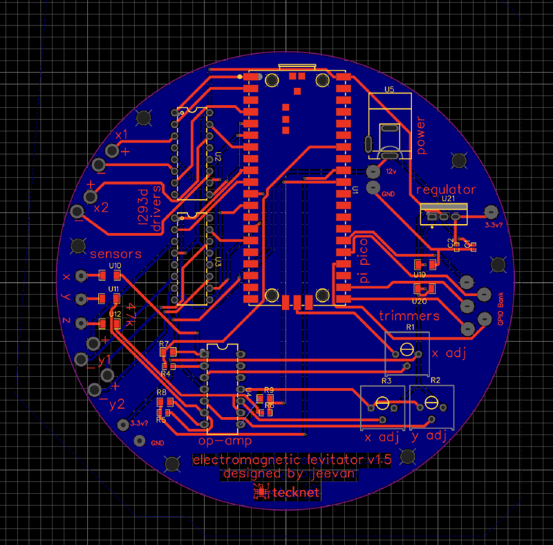
God I forgot how horrendous this was. To explain the components, we have a Pi Pico as our microcontroller, doing all the PID stuff. There are two L293D drivers which each drive two of the electromagnets. This IC, lets me control speed and direction, which would be needed to actually manipulate the platform. Down below we have the LM324, an op-amp used to amplify the input sensor values, so my microcontroller could actually register them. The 3 potentiometers were to tune the op-amp, and at the top, theres a linear voltage regulator to step down the 12V input to 3.3 volt so the Pi Pico could use it, and still retain 12V for the electromagnets. Since I knew no better, I decided to use 0603 package resistors (they’re reallllly small) since I thought I was that competent at soldering (I wasn’t).
The fab I decided to use for this had a lead time of 3 weeks, and it took me a month to get my hands on the board and components. Suffice to pretty much nothing worked. Well the L293D managed to work, since that was straight forward enough. My linear voltage regulator, which I hadn’t tested at all before was completely broken. I did manage to solder the resistors, but the solder joints were so bad, that I’m pretty sure I shorted some things. And to tie it all together, I soldered the Pi Pico to the PCB directly instead of through headers, and immediately shorted it. And that was it for the short lived first iteration. Lesson learnt. USE HEADERS!
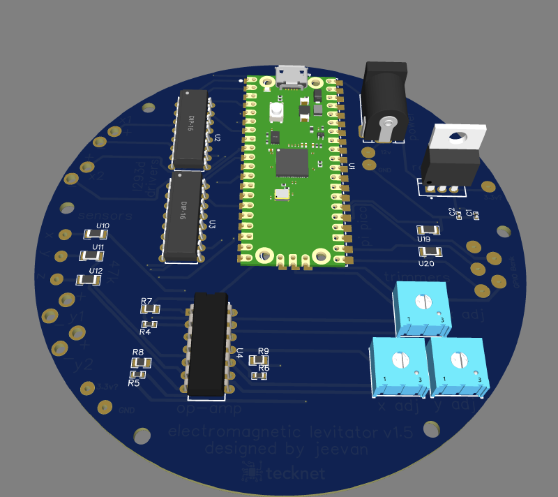
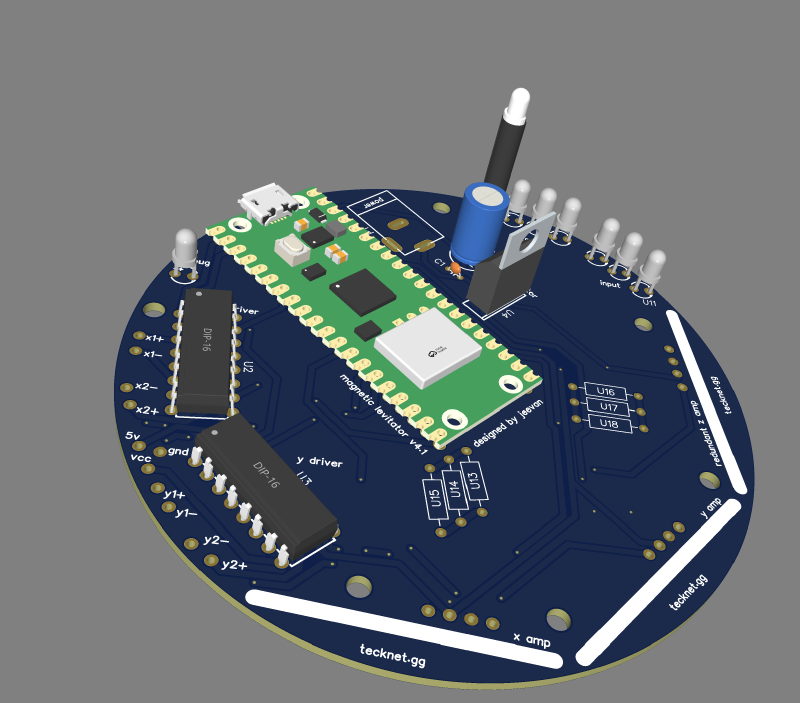
Things did get better with the second iteration. Much better.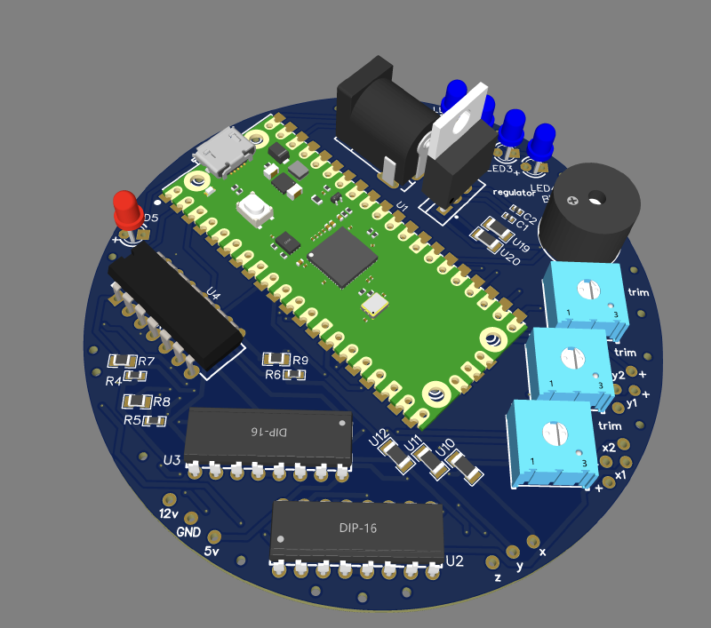
Seemingly I failed to learn my lesson with the resistors. But overall, much better designed. I don’t remember if I ever fabricated this, but this was one of the many intermediate iterations I have.
I think there was an actual 2nd iteration that I did fabricate, but I might have switched back o KiCAD from EasyEDA for that one. I had this whole phase where I switched between EasyEDA, and Altium Designer and KiCAD. From my experience Altium is overkill. KiCAD is really good, but the parts integration is annoying. EasyEDA is sketchy since its cloud-based, but EasyEDA, hand-down had the most convenient parts library. Plus really tight integration with JLC-PCB, my now go to fab-house. For anyone starting out, if you’re willing to cede the benefit of cloud based software, definitely learn KiCAD, its more powerful, and FOSS, which is always a big plus.
Getting back on track, after my supposed 2nd iteration, I finally accepted that I wasn’t competent enough to design my own op-amp systems just yet, and so I found some sensor modules on Amazon, with amplifiers built in, and resorted to frankensteining that to my board.
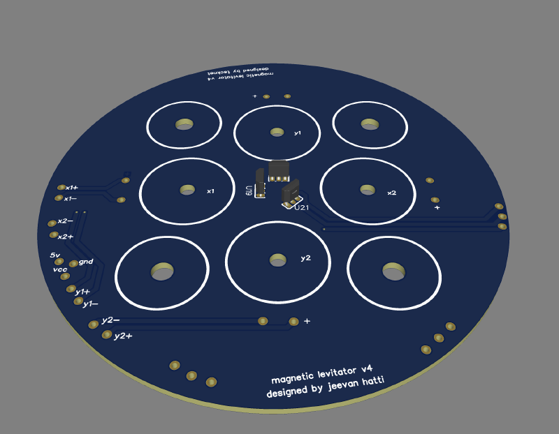
And that leads us to the first design that somewhat works. Yes the traces are horrible. Worse than the second. But it worked. Pretty well believe it or not, all the sub-systems were seemingly sound. Progress was made. After another few hours, I had the top PCB designed too (the one that would house the electromagnet and sensors).
With all the hardware seemingly working now, I could move onto coding.
Ok I was lying to you. The hardware wasn’t “all” working. The op-amps were giving me a lot of trouble, and we’re rather patchy, not to mention that tuning was hell. When I started coding, I spent more time debugging the hardware, and it was pretty obvious that this wasn’t going anywhere. I was, and still am confident, that with one more holistic re-design I could get a fully functional hardware platform. But at the time, I had already been working on this project on and off for a year, and I had to catchup with the year of GCSE content that I wasn’t there for.
And so this project went to die. Sure now that I look at it, I was probably only 25% of the way there, taking into consideration the timeline of other projects since. The software would have taken a long time, especially with the inherent instability of what I’m trying to achieve. But I think I learnt a fair few things regarding taking on projects of similar sizes.
To summarise. Kill your ego before you start, and don’t be utterly delusional. I think if you follow those two pieces of advice, you have a solid chance of succeeding, or at least not failing miserably, which in my eyes, is success.
On a more serious note, I did learn a lot from this. I’ve worked on multiple projects since, and they didn’t all end this horribly, which is a massive plus. 7/10 learning experience. Would do again.
If I do end up re-attempting this project, which I hope I do its really cool when it works.. I think a more integrated system would work far better. With my approach, all my subsystems were designed blindly, and I suppose they were just a bit off, and didn’t work together properly. At the time, switching to modules seemed like the right play, but I suppose it just doesn’t mesh well. Better designed systems, and actually testing them before fabricating, and I think I would have a much more pleasant time with this. Also python. I don’t want to code that in C++ even though it would be so much more performant. I think I would just bite the performance bullet and get myself a Pi Zero or something so I can just upload python scripts to it. And honestly after you get a working codebase, porting it to C++, while tedious, isn’t too difficult.
To put it simply, don’t hate yourself.
As I proof-read this, I realise I may have leant a bit into narration, more than I hoped so. I definitely skivvied off on the technical aspects, mainly since it would take me an eternity to find all of my design documents and notes. I can’t even manage to locate the 4 lines of firmware I wrote. For future write ups, I will go more into depth with the technical aspects, since I should have most of it documented now. For some significantly better resources on this projects, I’ve attached some links below.